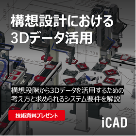
What is the 3D CAD required for semiconductor manufacturing equipment design?
3D CAD that achieves a reduction in lead time for semiconductor equipment development! Realizing ultra-fast response handling of 3 million parts in 0.2 seconds.
In recent years, the development of semiconductor manufacturing equipment has seen a tremendous increase in the number of components due to the complexity of the required functions. Therefore, the biggest challenge is how to efficiently arrange various mechanical devices within a limited space. 'iCAD SX V8' is a domestically developed 3D CAD specialized for mechanical design, created to support Japanese manufacturing. iCAD achieves high-speed response, handling 3 million components in 0.2 seconds, allowing for stress-free design consideration and verification of the entire semiconductor manufacturing equipment, which can involve tens of thousands of parts. Leveraging its ability to handle vast amounts of information, it is possible to accumulate and utilize design information necessary for equipment development, including piping, wiring, and control (movement), all within a single CAD data file. This data can be used across various scenarios and departments, from design to manufacturing, assembly, and maintenance. *Case studies from semiconductor manufacturing equipment manufacturers are currently available for limited viewing on a special website. Please click the link below to download.
basic information
【Features】 ■ 3D CAD for mechanical designers adopted by many top semiconductor manufacturing equipment manufacturers ■ Significantly reduces lead time for the entire equipment development, not just design ■ Proven track record of zero interference and substantial reduction in rework (Examples include a 25% reduction in design time and a 20% reduction in man-hours until drawings are completed) ■ Design for not only mechanics but also piping, wiring, and control (motion) is realized with a single tool (iCAD only) 【Challenges When Trying to Design with 3D CAD】 ■ Handling a vast number of parts leads to poor response, making it difficult to consider and verify the entire equipment ■ At the stage where the layout is not yet determined (design changes occur frequently), conditions are not fixed, making it impossible to conduct conceptual discussions with history-based 3D CAD that requires prior determination of component configuration (constraints and history are bottlenecks) ■ Mechanics and piping can only be considered with separate tools, making it impossible to review interactions between them during discussions *For more details, please refer to the PDF document or feel free to contact us.
Price information
Mid-range 3D CAD
Delivery Time
Model number/Brand name
3DCAD iCAD SX for Mechanical Designers
Applications/Examples of results
【Applications】 ■ Design of semiconductor manufacturing equipment ■ Various design verifications (interference, operation) ■ Automation of various ancillary tasks (automatic output of reports and parts lists, error checking) ■ Visualization of assembly procedures, accumulation of know-how *For more details, please refer to the special site for case studies on the introduction of 3DCAD iCAD SX for mechanical designers.
Related Videos
catalog(8)
Download All CatalogsRecommended products
Distributors
To support Japan's manufacturing, iCAD Corporation has developed the specialized 3D CAD software 'iCAD SX V8' focused on mechanical design. iCAD achieves high-speed response, handling 3 million parts in just 0.2 seconds, allowing for stress-free design consideration and verification of large-scale equipment and entire production lines that can consist of tens of thousands of components. By leveraging its ability to manage vast amounts of information, it is possible to accumulate and utilize the design information necessary for equipment development, including piping, wiring, and control (movement), all within a single CAD data set. This single data set can be used across various scenarios and departments, from design to manufacturing, assembly, and maintenance. This leads to a reduction in development lead time and an improvement in design quality.


