news list
1~9 item / All 9 items
-
Beginner's 3D CAD Creo Parametric Usage Tutorial Series Volume 7 Now Available!
The seventh installment of the beginner-friendly 3D CAD Creo Parametric tutorial series focuses on features suitable for designs using frames, such as aluminum and sheet metal. It allows for easy implementation of 3D solid structures.
-
The future of design changes with the cloud! Introducing "Creo+", a SaaS version of 3D CAD for the manufacturing industry.
Always able to use the latest features without version upgrade work. Simultaneous design reviews and edits by multiple people are possible, making global/multi-site collaboration easy!
-
Direct utilization of 2D drawings within 3D CAD.
The use of 3D CAD in mechanical design varies depending on the customer's situation, with some companies having been using it for over 20 years and others just starting recently. According to data from December 2019, over 60% of companies are designing using 3D data. However, the methods of design instruction to partner companies show that 54.3% use drawings, 23.8% use 2D data, and when combined, about 78.1% of design instructions are given in 2D. In this context, when companies that have traditionally designed using 2D CAD adopt and utilize 3D CAD, discussions about "whether past 2D CAD data can be utilized" are frequently heard in our sales activities, not just regarding operational training and usage. The intention here is not to question the appropriateness of using past 2D data in 3D CAD, but to describe how to technically utilize 2D CAD data in 3D CAD using the feature "AutobuildZ" included in the basic package of Creo Parametric. Please check the details via the link.
-

Creo Brothers Presents "Clio's Room" - Thermal Conductivity Analysis and Thermal Fluid Analysis -
PTC Japan has launched "Creo Brothers Presents 'Creo's Room'" on YouTube, featuring our skilled engineers. This time, we will introduce "Thermal Conductivity Analysis and Thermal Fluid Analysis." Both thermal conductivity analysis and thermal fluid analysis are useful for analyzing heat transfer and determining temperature distribution. The former can be executed with simple operations but is suited for analyses that do not require high precision, while the latter allows for various conditions to be set and is suitable for analyses that demand accuracy. We will explain the capabilities of these two analyses, the differences in thinking, and the differences in analysis scope, based on explanations and actual analysis examples. For more details, please check the link.
-

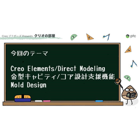
Creo Brothers Presents "Clio's Room" - Creo Elements/Direct Modeling Mold Cavity/Core Design Support Features
At PTC Japan, we have launched "Creo Brothers Presents 'Creo Room'" on YouTube, featuring our skilled engineers. This time, we will introduce the "Mold Design Support Features for Cavity/Core Design in Creo Elements/Direct Modeling." Creo Elements/Direct Modeling includes Mold Design support features for cavity and core design. In this video, we will briefly introduce the overview of Mold Design. For more details, please check the related links.
-
Creo Brothers Presents "Clio's Room" - Assembling the Same Parts in Different States -
At PTC Japan, we have launched "Creo Brothers Presents 'The Room of Creo'" on YouTube, featuring our skilled engineers. This time, we will introduce "Assembling the Same Part in Different States." Have you ever wanted to change the model's state between the part and assembly? For example, a spring is at its natural length when it's a part, but it stretches or compresses when assembled. Additionally, when placing multiple instances of the same spring, it needs to have different states depending on its location, even though it's the same part. We will introduce Creo's functionality for assembling the same part in different states. Please check the related links for more details.
-
Creo Brothers Presents "Clio's Room" - Creating 3D Models from Scan Data -
At PTC Japan, we have launched "Creo Brothers Presents 'The Room of Creo'" on YouTube, featuring our skilled engineers. This time, we will introduce "Creating 3D Models from Scan Data." This is an introduction to the reverse engineering capabilities of Creo Parametric. It is a function that creates 3D models from point cloud data obtained by 3D scanning physical objects. It is used when there is a physical item but no 3D data available, and it serves purposes such as creating 3D models to compare 3D CAD design data with actual physical products, or to conduct structural or fluid analysis on reference physical items. For more details, please check the related links.
-
Creo Brothers Presents "Clio's Room" - Creating Arrangement Drawings from Wiring Models -
PTC Japan has launched "Creo Brothers Presents 'The Creo Room'" on YouTube, hosted by our skilled engineers. This time, we will introduce "Creating Assembly Drawings from Wiring Models." We will present the Harness Manufacturing Extension, a feature that allows you to quickly create 2D drawings from wiring models created using the wiring design function PCX in Creo Parametric. For more details, please check the related links.
-

[3DCAD Blog] Extension for Streamlining Wiring and Piping Design: Creo Piping and Cabling Extension (PCX)
By utilizing PCX, wiring and piping design in 3D CAD becomes faster, allowing for early detection and correction of issues. For more benefits, please check out the blog article.